

We’re here to help
Let us help you
Melt mass-flow rate is an industry-standard method used to quickly gain a feel for the viscosity of a polymer in its melted state, which is the state in which most thermoplastics are formed into useful products.
The method has been in use for many decades, having originated in the ICI laboratories following the commercial development of polyethylene in the 1930s. Due to its simplicity and accuracy, it forms the basis of many companies' incoming quality control programmes.
The measurement is performed in a standardised manner, with the two recognised incumbents being the European ISO standard and the American ASTM equivalent. In the early days of the measurement, the term most often used was melt flow index or simply MFI. However, both standards have superseded this by melt mass flow rate, or MFR.
This seemingly semantic change is important because the term MFI is still widely used today, so any practitioner will encounter it regularly when, in official terms, it should only ever be referred to as MFR. The ASTM standard acknowledges this potential confusion in its note 27; thus, ‘It has become customary to refer to the flow rate of polyethylene as “melt index” when obtained under Condition 190/2.16.
However, for all other materials, the use of melt index or any term other than “flow rate” is discouraged, regardless of the condition used’. No mention of MFI is present in the ISO standard; consequently, in this article, only the term MFR will be used, and the standard referred to will be the ISO version.
It is important to appreciate that an MFR value is not a measurement of viscosity but is indicative of it; MFR is measured in g/10mins and viscosity in Pas, so MFR is, in fact, a mass flow rate. There is good reason for this approach, not least because measuring melt viscosity requires a substantially more complex technique, involving more costly instruments and, probably of most importance, more time.
An MFR measurement can be produced within 25 minutes and often considerably less, depending on the polymer. The measurement is also a one number technique, making the result easy to understand, requiring no interpretation skills. In concert with the well written ISO1133 standard, an authoritative MFR value can be produced with a minimum of operator training.
An MFR value is most often used to compare polymers, assess batch to batch variation, and accept or reject incoming deliveries. When comparing generic polymers and/or polymer grades, a simple difference in MFR value can indicate which grade may be more suitable for a particular process.
Additionally, when none is expected, a difference in MFR value can warn of potential problems due to batch to batch variation or mistaken grade selection. The quality system aspect of MFR is associated with assessing whether a delivered batch of polymer is fit for purpose.
Thus, a sample of an incoming delivery is taken for MFR testing before it is unloaded for use in the plant. The incoming polymer is usually accompanied by a certificate of conformity defining the allowable limits of the MFR value. Thus, if the returning MFR value is within the tolerance on the certificate, the load is accepted, creating a simple and efficient quality control system.
As stated earlier, MFR is not a viscosity but is indicative of it, demonstrated in figure 1. The figure shows the shear viscosity function of polypropylene as tested on a capillary rheometer at 230°C.
The thick black line describes the viscosity behaviour of the melt as it experiences an ever-increasing shear rate; note the viscosity reduces with increasing shear rate (pseudoplastic), meaning a one number test cannot describe the entire trend, unlike the straight line of the constant viscosity Newtonian oil shown in red.
MFR is a constant stress experiment, and since shear viscosity is the product of dividing shear stress by shear rate, it follows that the constant stress of an MFR test, provided by the particular test mass, will appear as a line falling across the viscosity function.
The intercept of the line of constant stress and the viscosity function is the indicative viscosity. In the case shown, the blue line of constant stress resulting from a 2.16kg MFR test mass results in an indicative viscosity of around 2500Pas at a shear rate of 6.76s-1; for the 5.0kg mass, the indicative viscosity is 850Pas at a shear rate of 43.3s-1.
Figure 1 also highlights that the shear rates at which an MFR test is conducted are low and influenced by the viscosity of the polymer itself.
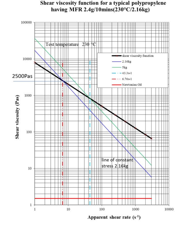
Figure 1 The shear viscosity function of polypropylene at 230°C with standard MFR masses is shown as lines of constant stress to highlight the indicative viscosity values and effective shear rates of an MFR test.
An additional benefit of an MFR value is that it is very sensitive to changes in viscosity which are in turn sensitive to the polymer molecular architecture, specifically, average molecular weight (M); a low MFR number indicates a high M, and a high MFR will suggest the converse, indicating low M.
An MFR value is inversely proportional to viscosity and M, so the reader may forgive themselves for making the inevitable, time-honoured mistake of getting it the wrong way round!
MFR is a relatively simple test to perform and fundamentally consists of a heated barrel, a piston, a mass and a die. Figure 2 shows a modern Hanatek MFR instrument with the test mass dynamically moving down under gravity with the piston located in the barrel.
The barrel is loaded with the polymer of interest and heated to the specific test temperature, often 190°C or 230°C. The polymer is driven through the die under the action of the piston and mass assembly and the extrudate collected at specific time or distance intervals.
The extrudate collected at each interval, the cut-off, is then weighed and a mass achieved for each, and from knowledge of the standardised barrel diameter, a displaced volume is calculated. Once the displaced volume is known, the cut-off mass is divided by it to calculate the melt density from which the mass flow rate is achieved and extrapolated to the standardised time of 10 minutes.
Consequently, MFR values are always measured in g/10mins, and importantly must show clearly the prefix confirming the mass and temperature used; for example, 2.1g/10min(190°C/2.16kg).
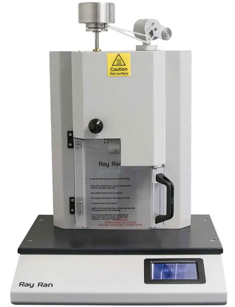
MFR300 Ray Ran Melt Flow Index Tester with digital display and caution hot surface label, used for measuring the flow rate of molten plastic.
The ISO standard ensures that this relatively simple test can be conducted with little operator training and be largely operator and instrument independent. The important standard items are the mass and piston, the barrel and die dimensions, temperature control and the timing mechanism.
The barrel is standardised at a nominal diameter of 9.55mm and is of hardened steel construction which resists wear from most polymers, and the die has a length of 8mm and a nominal diameter of 2.095mm. Dies are generally manufactured of tungsten carbide for the same wear resistance and accuracy; the die diameter tolerance is ±5µm. The other salient considerations are load time, total test time, cut-off timing and length.
Loading usually takes less than a minute. A standard pre-heat time of five minutes is instigated to ensure the polymer takes up the temperature of the barrel and is fully melted. Once the pre-heat time has elapsed, the piston and mass assembly is allowed to move under the action of gravity, pushing the melted polymer out of the die, with measurement commencing at the start of a 30mm section marked on the piston.
Measurement ends when the upper mark passes into the barrel, with distance and time being determined by the instrument such that multiple MFR values can be obtained from one test. The standard suggests that the pre-set distance or time intervals be such that a cut-off length is between 10mm to 20mm; anything outside of these limits begins to compromise time and mass measurement.
The last measurement allowed must be no longer than 25 minutes from the end of barrel charging. Most instruments require the user to manually cut the extrudate off at the cut-off interval, and it is this function that is most likely to introduce error and operator sensitivity; some instruments have a time-controlled automatic cutter, but they are not suited to all polymers, so manual cutting will be almost inevitable with some materials and time/mass combinations.
As with all test methods, there is no substitute for practice and familiarity, and as experience grows, accuracy will improve, and operator dependence will reduce.
The ISO standard is specifically ISO 1133, and at the time of writing, it is version 2011, thus making the precise nomenclature, ISO 1133-1:2011. This detail is important because when employing this standard, the most up-to-date version must be used and referred to in this way, and failure to do so contravenes the standard, a point lost on many users who incorrectly state ISO 1133.
The standard also allows three additional measurements to be calculated; MVR, melt density and FFR. MVR or melt volume flow rate, measured in cm3/10mins, is less frequently used and has the advantage of not requiring the extra work of making the cut-offs. Melt density (not to be confused with solids density) is also readily available since the pre-requisites, measured interval volume and cut-off mass, are an intrinsic part of the MFR calculation; melt density is the product of the cut-off mass divided by the interval volume.
Melt density is an important inflow simulation, so this measurement effectively comes for free! The lesser-used flow rate ratio, or FRR, is determined by dividing two MFR values derived from different masses (for the same temperature and polymer), so in figure 1, a FRR value could be obtained by dividing the MFR value from the 2.16kg test by that of the 5kg test. This value is sensitive to the molecular weight distribution, MWD.
In conclusion, MFR is an industry-recognized, rapid one number test that is sensitive to changes in polymer batch and type, lends itself to forming a quality control system and requires minimal operator training.
Furthermore, its standardised nature removes the need for operator interpretation and offers the additional benefits of MVR, FRR and melt density. The technique has stood the test of time and continues to be a staple of the polymer production and processing community.
Dr Don Fleming
Fleming Polymer Testing Ltd was established by Dr. Don Fleming in 1998 who thus has over 20 years’ experience in the polymer industry. Don graduated in Mechanical Engineering at Bradford University before undertaking a PhD in the same department. The substantive areas of his research were the reactive extrusion of cross-linked LLDPE and PET foams via twin screw extrusion.
Having written and presented many papers over the years, juggled with extruder dies, and having his hands burnt on many occasions by a variety of polymer melts, has cemented both the practical and theoretical aspects of rheology.
Let us help you